Digital Twin of a 3D-Printing Construction Robot
A full-scale machine that 3D-prints a dome-shaped house from sludge, for rapid housing after natural disasters: mechanical design, electrical design and a digital twin in Siemens NX.
Problem and motivation
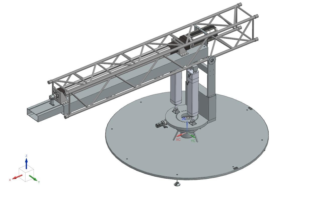
After a natural disaster, shelter is needed fast and cheaply. The concept is a machine that stands on site and prints a house of a predefined shape from sludge. It has three axes, each with its own drive: rotation of the whole structure, elevation of the arm, and translation of the arm that carries the nozzle.
The printed house
The house is a dome with a sunroof and a door opening, printed layer by layer as the machine rotates and the arm rises. The house radius and the door’s width and height are parameters in the PLC program, within their permissible ranges. The video above is the nozzle’s path for one such house, traced in the digital twin.
My part: the elevation module
- Design and CAD. I modelled the elevation module in Siemens NX: the truss arm, its hinge and bearings, and the actuator mounts.
- Actuator sizing. The worst case for the actuators is a horizontal arm. Placing them 0.34 m from the hinge balances the required force against the stroke, and a 1 m concrete-filled counterweight at the back of the truss brings the total force down to 40 kN, shared by two linear actuators. The arm has to reach 80°, which needs at least 300 mm of stroke; I selected the Tolomatic IMA 55 (457 mm stroke).
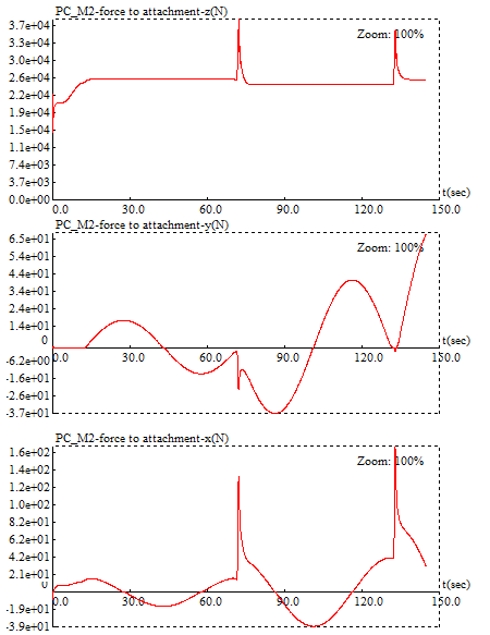
- Digital twin. I built the elevation module’s part of the digital twin in NX Mechatronics Concept Designer. The simulation confirmed that one actuator cannot carry the load alone, and showed force spikes at every change in position that damping did not remove, so the recommendation was acceleration control through a variable-frequency drive.
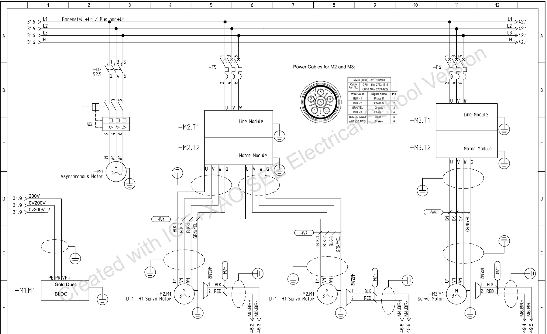
- Electrical design and safety. I drew the complete electrical diagram set in SEE Electrical, and took part in the risk assessment and safety functions (EN ISO 12100, EN ISO 13849).